Table of contents
- Safety First!
- One pump, controlled by microcontroller
- One pump, one solenoid valve, both controlled by microcontroller
- One pump, one solenoid valve, one pressure sensor, all controlled by microcontroller
Depending on your inflation needs, you might need only one pump, or a variety of pumps, solenoid valves, and pressure sensors. Here are some common configurations you might consider.
Safety First!
External power supply: Many pumps draw 12V, 300mA. This is too much for your Arduino (or other microcontroller) and laptop to power. To solve this, you need an external power supply. This can be a 12V adapter or a power bank that can deliver the required voltage. The diagrams below all include an external power supply.
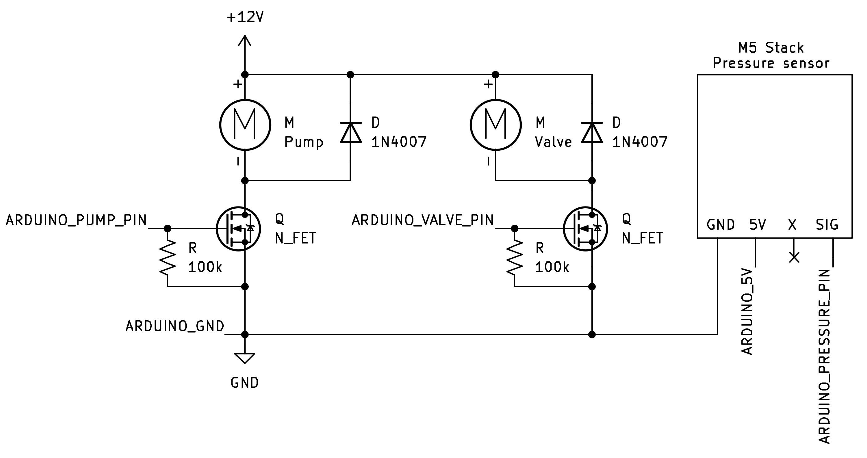
Flyback diode: On the inside of the pump are magnets and a coil. When the coil is powered, the magnets start rotating the motor, and the pump starts pumping. When the power is turned off, the magnets will still rotate for a little bit, thus generating current in the coil, which then reverses back into the circuit, and which can harm other components or the power supply. For this reason, you need to add a flyback diode to the circuit, so that this excess current can dissipate through the motor itself. The flyback diode has been included in each circuit. Notice the polarity: the negative terminal of the diode is connected to the positive terminal of the pump, and vice versa, because the current generated by the motor comes into the circuit in reverse!
One pump, controlled by microcontroller
Needed:
- 12V pump (e.g. 370A link)
- 12V power supply (e.g. 12V, 2A link)
- N-channel MOSFET (e.g. IRF740 link)
- general purpose diode (e.g. 1N4007 link)
- microcontroller (e.g. ESP32 C3 Zero link)
- 100k resistor
Schematic
Schematic of the circuit. Make sure the ground of the Arduino is also connected to the ground in the circuit. The pump is placed in between the 12V source and the mosfet. This is called low-side switching. To learn more about high-side and low-side switching, see this webpage: link. We are using the mosfet like a water tap: when you turn a tap, water flows out. When you apply a high enough voltage to the gate of the mosfet, it will let current pass through (simplified explanation).
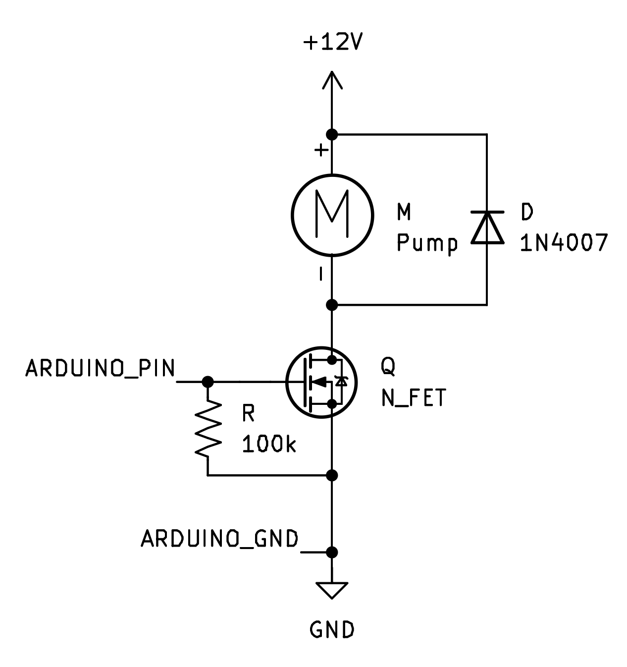
Falstad
You can try out and edit the circuit here: Falstad simulator - 1 pump
Example breadboard layout
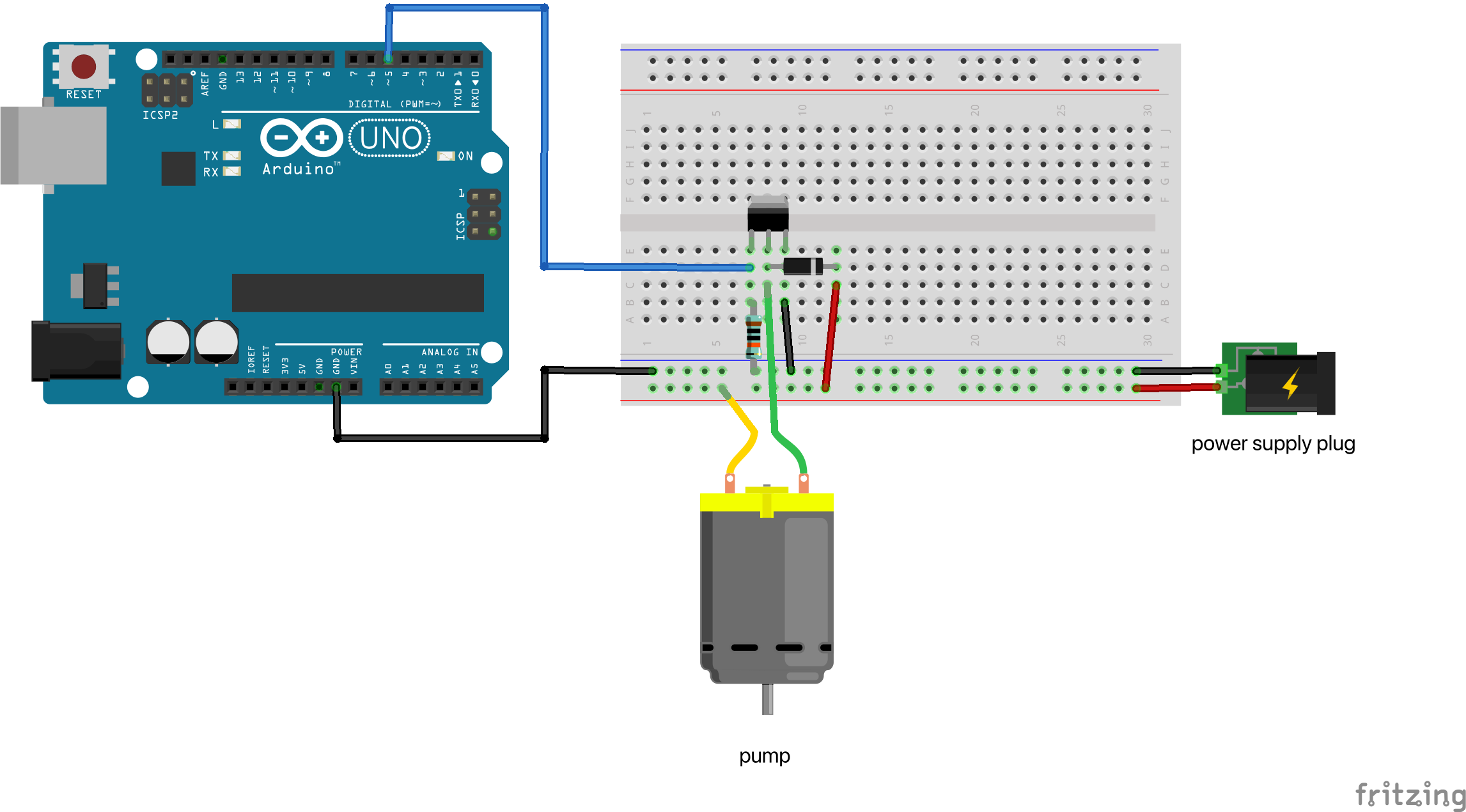
Arduino code snippet
Make sure the microcontroller pin that controls the mosfet is a PWM pin. On Arduino Uno these pins have a ~ symbol next to them. On most newer microcontrollers, all pins are PWM. PWM stands for pulse-width modulation. This allows you to send signals with a varying duty cycle, for example high 25% of the time, and low 75% of the time. The highs and lows alternate very quickly. On 5V logic, this means that the output signal will resemble an output of 0.25*5V=1.25V. That way, you can ‘open’ the mosfet only a little bit or fully, depending on the duty cycle you send. You can find the Arduino PWM documentation here: link.
const int pumpPin = 5; // The pin that connects to the mosfet
int percentage = 50;

// The PWM value normally goes from 0 (0%) to 255 (100%).
// We need to convert to a value between 0 and 255 (255*(100/percentage)) for the code to work.
analogWrite(pumpPin,255*(100/percentage);
One pump, one solenoid valve, both controlled by microcontroller
Needed:
- 12V pump (e.g. 370A link)
- 12V normally closed solenoid valve (anything 12V, e.g. Tailonz 2v025-08. Try Amazon, AliExpress, etc.)
- 12V power supply (e.g. 12V, 2A link)
- 2x N-channel MOSFET (e.g. IRF740 link)
- 2x general purpose diode (e.g. 1N4007 link)
- microcontroller (e.g. ESP32 C3 Zero link)
- 100k resistor
Schematic
Schematic of the circuit. Make sure the ground of the Arduino is also connected to the ground in the circuit. The pump is placed in between the 12V source and the mosfet. This is called low-side switching. To learn more about high-side and low-side switching, see this webpage: link. We are using the mosfet like a water tap: when you turn a tap, water flows out. When you apply a high enough voltage to the gate of the mosfet, it will let current pass through (simplified explanation).
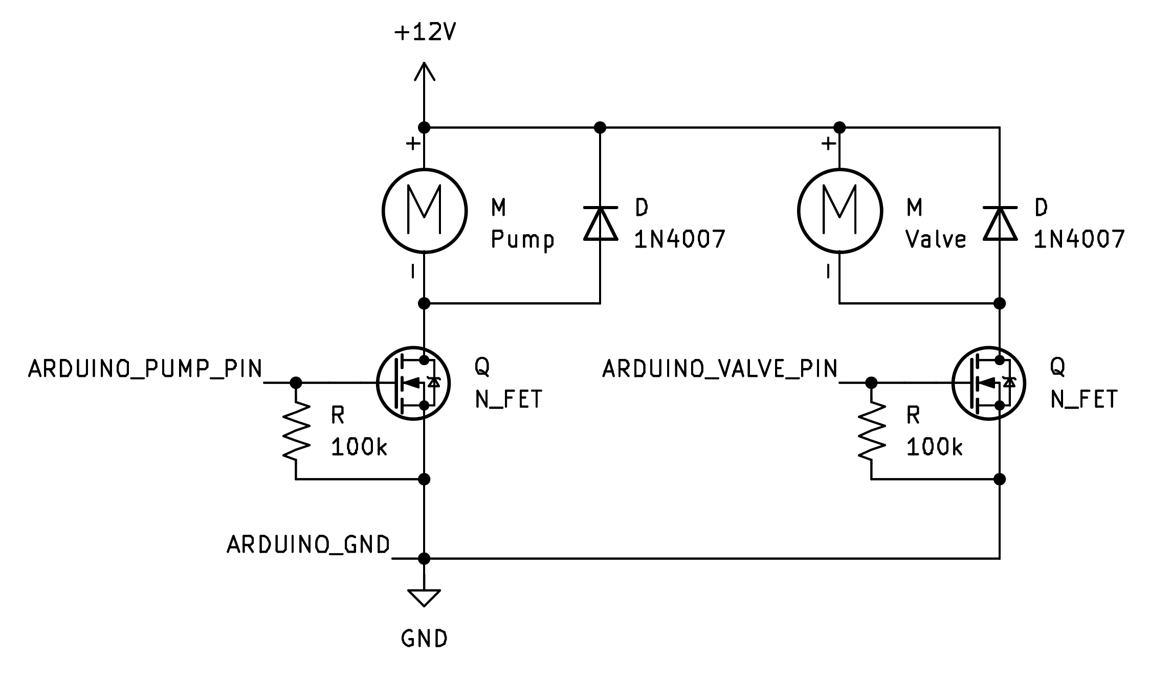
Falstad
You can try out and edit the circuit here: Falstad simulator - 1 pump, 1 solenoid
Example breadboard layout
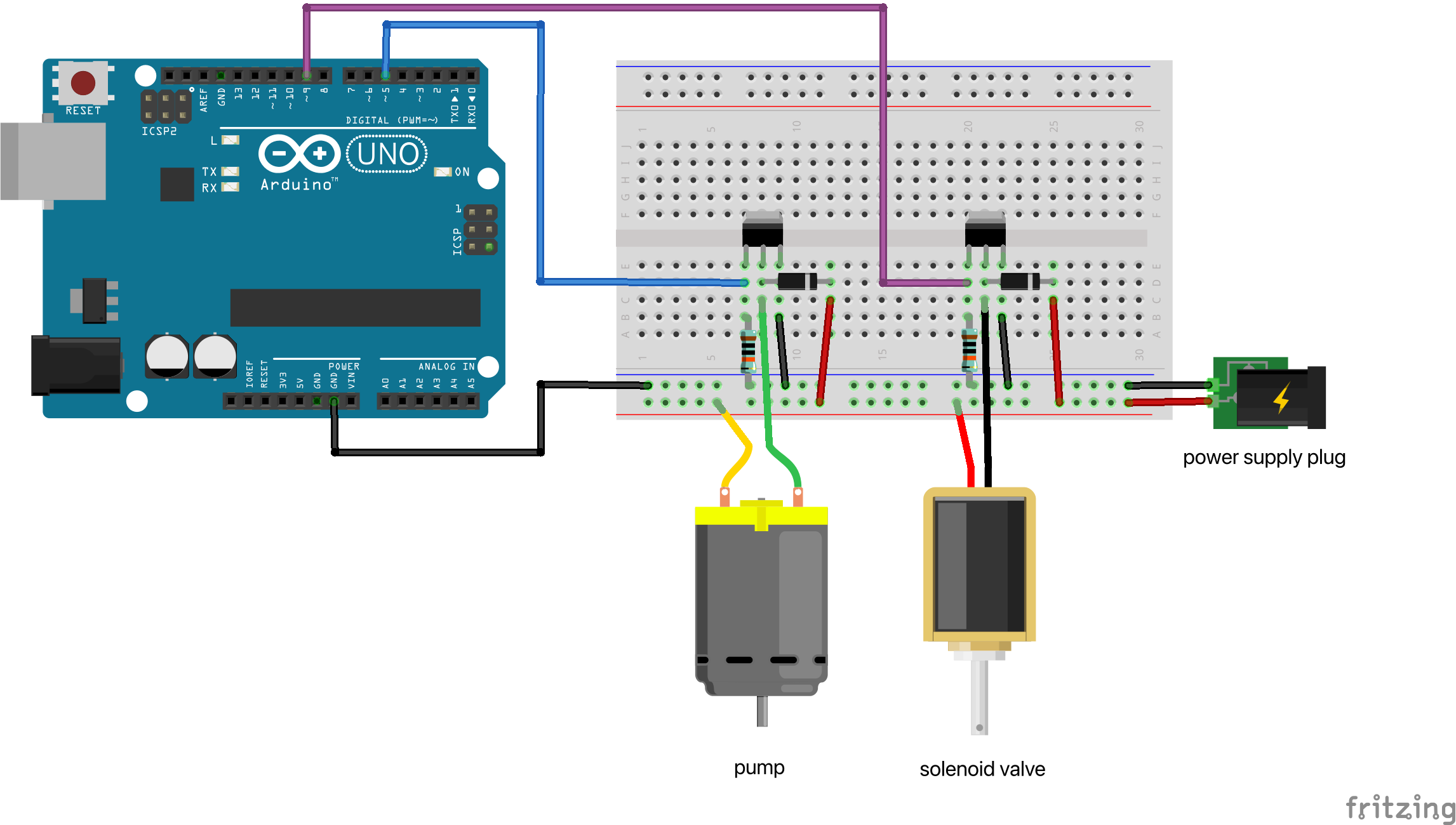
Arduino code snippet
Make sure the microcontroller pin that controls the mosfet is a PWM pin. On Arduino Uno these pins have a ~ symbol next to them. On most newer microcontrollers, all pins are PWM. PWM stands for pulse-width modulation. This allows you to send signals with a varying duty cycle, for example high 25% of the time, and low 75% of the time. The highs and lows alternate very quickly. On 5V logic, this means that the output signal will look like 0.25*5V=1.25V. That way, you can ‘open’ the mosfet only a little bit or fully, depending on the duty cycle you send. Note that you can only PWM the pump, not the solenoid, as the solenoid is only fully open or fully closed. The solenoid has no intermediate state where it’s a bit open or closed. Those solenoids do exist (proportional solenoid valves) but they’re much more expensive. You can find the Arduino PWM documentation here: link.
const int pumpPin = 5; // The pin that connects to the pump mosfet
const int valvePin = 9; // The pin that connects to the valve mosfet
int percentagePump = 50;
int stateValve = HIGH; // HIGH = 5V on Arduino and turns on the solenoid. LOW = 0V and turns off the solenoid

// The PWM value normally goes from 0 (0%) to 255 (100%).
// We need to convert to a value between 0 and 255 (255*(100/percentage)) for the code to work.
analogWrite(pumpPin,255*(100/percentagePump);
digitalWrite(valvePin,stateValve); // Here we can use digitalWrite, not a PWM signal, as we only use HIGH and LOW
One pump, one solenoid valve, one pressure sensor, all controlled by microcontroller
Needed:
- 12V pump (e.g. 370A link)
- 12V normally closed solenoid valve (anything 12V, e.g. Tailonz 2v025-08. Try Amazon, AliExpress, etc.)
- pressure sensor (e.g. M5Stack Tube-Air pressure unit link. Or, if you’re feeling adventurous, try the MCP-H10 or XGZP6847A pressure sensor from AliExpress)
- 12V power supply (e.g. 12V, 2A link)
- 2x N-channel MOSFET (e.g. IRF740 link)
- 2x general purpose diode (e.g. 1N4007 link)
- microcontroller (e.g. ESP32 C3 Zero link)
- 100k resistor
Schematic
Schematic of the circuit. Make sure the ground of the Arduino is also connected to the ground in the circuit. The pump is placed in between the 12V source and the mosfet. This is called low-side switching. To learn more about high-side and low-side switching, see this webpage: link. We are using the mosfet like a water tap: when you turn a tap, water flows out. When you apply a high enough voltage to the gate of the mosfet, it will let current pass through (simplified explanation).
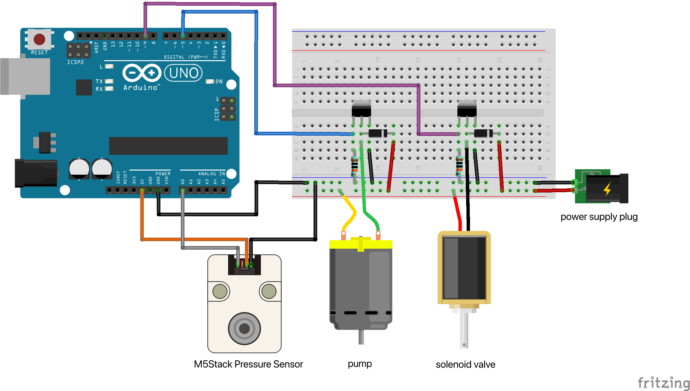
Example breadboard layout
Arduino code snippet
Make sure the microcontroller pin that controls the mosfet is a PWM pin. On Arduino Uno these pins have a ~ symbol next to them. On most newer microcontrollers, all pins are PWM. PWM stands for pulse-width modulation. This allows you to send signals with a varying duty cycle, for example high 25% of the time, and low 75% of the time. The highs and lows alternate very quickly. On 5V logic, this means that the output signal will look like 0.25*5V=1.25V. That way, you can ‘open’ the mosfet only a little bit or fully, depending on the duty cycle you send. Note that you can only PWM the pump, not the solenoid, as the solenoid is only fully open or fully closed. The solenoid has no intermediate state where it’s a bit open or closed. Those solenoids do exist (proportional solenoid valves) but they’re much more expensive. You can find the Arduino PWM documentation here: link.
const int pumpPin = 5; // The pin that connects to the pump mosfet
const int valvePin = 9; // The pin that connects to the valve mosfet
const int sensorPin = A0; // The pin that connects to the pressure sensor
int percentagePump = 50;
int stateValve = HIGH; // HIGH = 5V on Arduino and turns on the solenoid. LOW = 0V and turns off the solenoid

// The PWM value normally goes from 0 (0%) to 255 (100%).
// We need to convert to a value between 0 and 255 (255*(100/percentage)) for the code to work.
analogWrite(pumpPin,255*(100/percentagePump);
digitalWrite(valvePin,stateValve); // Here we can use digitalWrite, not a PWM signal, as we only use HIGH and LOW
int sensorValue = analogRead(sensorPin);
Serial.println(sensorValue);